Cosmos: Smart LEDs
Content
Functional Block Diagram
The figure below, shows the functional block diagram of the Cosmos: Smart LEDs. It makes use of the ESP8266-12E WiFi chip to communicate with the centralized controller. The obstacle in this module that had to be overcome, was to deal with the 12 volt input requirement of the LEDs and the 3.3V requirement of the ESP8266. In contrast to the LM1117; LM2596 was used to satisfy both the requirements. The TIP-122 transistor is used for amplification of current from the ESP8266 to allow for translation of the digitally encoded values of the red, blue and green signals into an amplified version that can be recognised by the RGB LED strip. It simultaneously also works as a switch, when only one of the colours in the strip are to be made visible.

Technical Overview
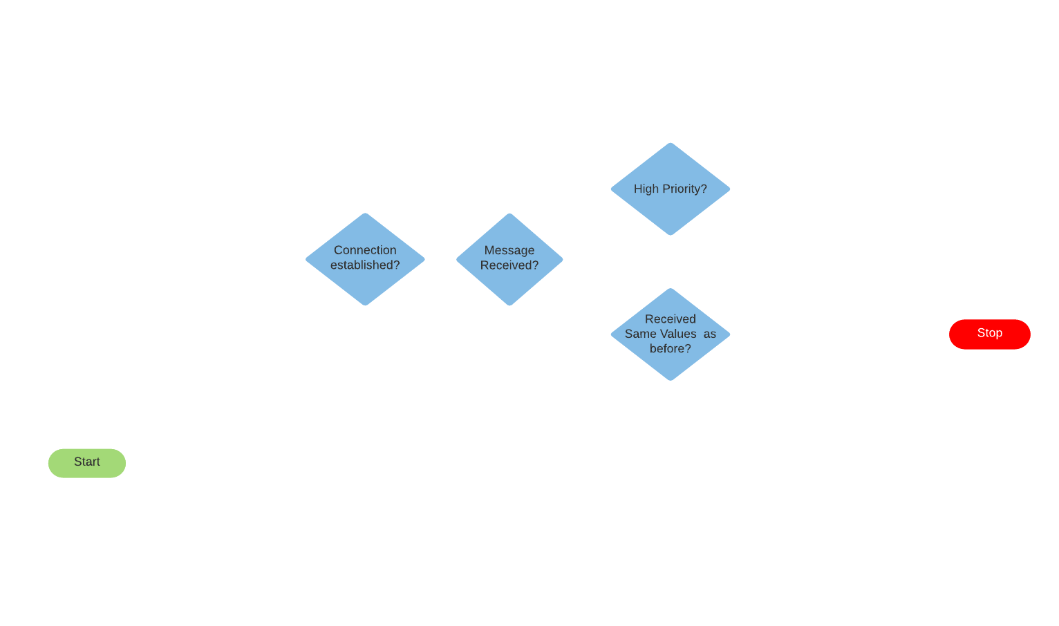
Flowchart
ESP8266 chip, when it receives the RGB values from the centralized controller, sends the corresponding signal onto the Red, Green, and Blue channel of the light strip. This helps to manually control the light strip. When the broker receives a message from other connected end-points, for instance the COSMOS: Fire Sensor, it checks for the rules set in the .Rules file. Based on the predefined conditions takes the necessary actions.
The Cosmos: Smart LED (CSL) initially boots up and repeatedly tries to connect with the MQTT broker, RPi3, till a successful connection is established. Once the link is confirmed, the RPi3 would publish the initial state of CSL. The CSL, then waits for a message from the broker, which would indicate the action that it has to perform. For instance, consider the following message being sent by the broker to the CSL module —`100;100;100` as mesgRecvd, which translates to a white light light. The mesgRecvd is stored as a string, and broken down by the separator ‘;’ and the corresponding red, green and blue values are stored as an integer. This integer value is checked, if it is the same as the previous message sent, to prevent redundant message transfer. The digital values of the corresponding colours are then mapped to the values of the signal that is to be sent to the light strip. Once the signal is processed, it checks if another message has been received. If the next mesgRecvd is `0;0;0`, it would simply turn off the strip.
Please note that, since the database is already in place, and all state changes are persisted, the states of CSL are persisted as well. However, they are not represented on the dashboard due to insufficient transference of meaning.
Final Product
